If your motor keeps tripping “for no reason,” it usually has a reason—you just don’t have enough visibility (or the protection isn’t modeling the motor’s heat correctly). Electric motor overload protection is not primarily about cutting off high current. It’s about protecting insulation life by preventing excessive temperature rise over time, while still allowing legitimate events like starting current and short-duration torque spikes.
In this deeper, more professional guide, we’ll approach electric motor overload protection the way reliability engineers and panel designers do: thermal modeling, trip dynamics, coordination with short-circuit protection, VFD/soft starter interactions, and practical commissioning tests that stop nuisance trips without sacrificing protection.
Overload protection is protecting temperature, not “amps”
A motor rarely fails because current went high for a moment. It fails because heat accumulates and the winding insulation degrades. That’s why serious electric motor overload protection approximates the motor’s heating and cooling behavior.

The real physics (simplified)
- Copper losses scale roughly with I²R, so heating grows quickly with current.
- Cooling depends on motor design and airflow (which changes with speed).
- Repeated starts and high ambient temperature reduce thermal margin.
So an overload device should answer:
- How much thermal stress is accumulating right now?
- How long can the motor tolerate it before damage begins?
That’s why time-current behavior exists: the higher the overload, the faster the trip.
| Protection approach | What it “sees” | Why it’s useful | Where it can mislead you |
|---|---|---|---|
| Simple current threshold | Current magnitude | Easy and cheap | Start-up nuisance trips, poor thermal fidelity |
| I²t / thermal model | Heat accumulation | Closest to insulation reality | Needs correct settings and assumptions |
| Direct temperature feedback (RTD/PTC) | Actual winding temperature | Best thermal truth | Sensors, wiring, and compatibility required |
A key takeaway: the better your electric motor overload protection matches real thermal behavior, the fewer “mystery trips” you’ll have—while still preventing slow cooking.
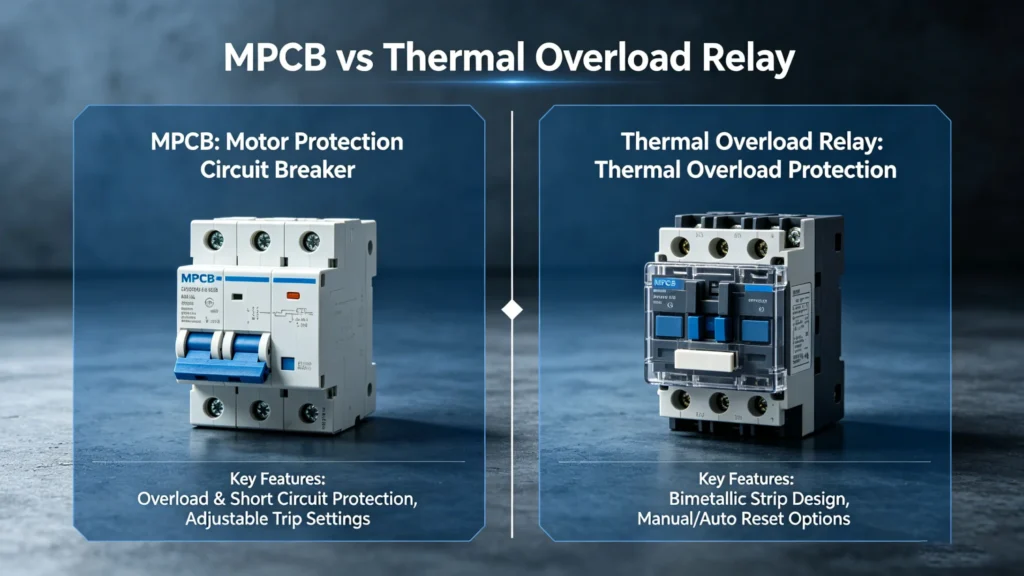
Device types: the real differences are accuracy and diagnostics
Most systems use one of three families:
- Thermal overload relays (bimetal/eutectic)
- Electronic overload relays
- Motor protection relays (MPRs) / “smart” protection modules
Thermal overload relays (classic)
These are robust and widely used in standard DOL and basic starter circuits. But ambient temperature, enclosure heat, and mounting can influence performance. Diagnostics are minimal: you typically get “tripped” and not much else.
Electronic overload relays
Electronic designs measure current more consistently and can implement richer thermal models. They also commonly add:
- phase loss detection
- phase imbalance
- stall/locked-rotor supervision
- underload/undercurrent (useful for pumps losing prime)
- event history
This is where electric motor overload protection starts helping you troubleshoot, not just trip.
Motor protection relays (MPRs)
These are built for critical assets and process uptime. They provide thermal capacity tracking, logs, and communications to PLC/SCADA. When downtime is expensive, this extra context is often worth more than the device cost.
| Type | Best fit | Advantages | Trade-offs |
|---|---|---|---|
| Thermal overload relay | Stable loads, low criticality | Simple, economical | Limited visibility, more ambient sensitivity |
| Electronic overload relay | Variable loads, troubleshooting needs | Better accuracy, more functions | Requires configuration discipline |
| MPR / smart protection | High downtime cost, data-driven maintenance | Logs, comms, thermal tracking | Higher cost, more engineering effort |
Trip dynamics: stop treating “trip class” like a guess
IEC users often encounter trip class (10/10A/20/30). The concept matters even if you’re not in an IEC environment: it’s a shorthand for how fast the overload trips at high multiples of current.
Don’t pick a higher class “just to avoid trips.” That’s how you end up protecting the process while sacrificing the motor.
| Trip class | Typical use case | What it tolerates | What it risks if misapplied |
|---|---|---|---|
| 10 / 10A | General duty | Normal start times | Nuisance trips on long acceleration |
| 20 | Higher inertia loads | Longer starting periods | Slower response to damaging overload |
| 30 | Very heavy start conditions | Very long starts | Delayed thermal protection |
For professional-grade electric motor overload protection, you should tie trip behavior to:
- measured start time (cold and hot)
- start frequency
- load torque profile (constant vs variable torque)
- worst-case ambient and cooling conditions
If you can’t explain why a trip class is chosen, you haven’t truly engineered the protection.
Specifications that actually control outcomes
Beyond “amp range,” the following specifications determine whether electric motor overload protection works as intended:
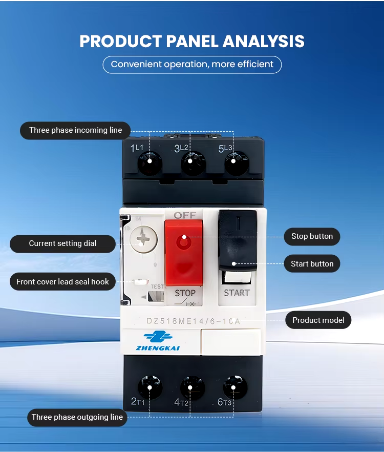
1) Setting range and resolution
Your device must cover the motor’s FLA with meaningful adjustment. Too coarse, and you’ll either nuisance trip or under-protect.
2) Phase loss / imbalance sensitivity
Single-phasing can destroy a motor quickly even if “average current” doesn’t look catastrophic at first. This feature is high ROI in harsh industrial power environments.
3) Reset strategy and restart risk
Manual reset forces investigation and reduces unsafe unexpected restarts. Automatic reset can be appropriate in very specific, engineered conditions—but it’s not a default.
4) Ambient compensation and enclosure heating
Thermal devices can drift with cabinet temperature. Electronic or compensated designs behave more predictably—especially in dense MCC sections.
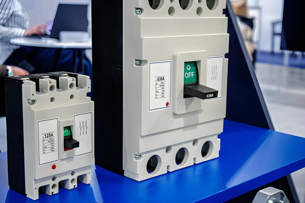
5) Coordination and SCCR impact
Overload protection does not replace short-circuit protection. Your upstream device selection (breaker/fuse) and the tested combination affect:
- coordination behavior (fault clearing damage)
- downtime after faults
- overall SCCR of the assembly
| Parameter | Why it matters | Common mistake |
|---|---|---|
| FLA setting | Defines thermal reference | Using “typical current” instead of nameplate/verified load |
| Phase loss | Prevents rapid heating | Not enabling it or setting too leniently |
| Reset mode | Controls restart safety | Auto reset with no restart risk analysis |
| Coordination | Determines fault damage and recoverability | Treating overload selection in isolation |
Coordination: overload protection must “play nicely” with short-circuit protection
Professional electric motor overload protection is part of a protection chain:
- short-circuit device (breaker/fuse) clears high fault current fast
- overload device manages thermal overload and abnormal running
- contactor executes switching and must survive expected duty
- control logic defines alarms, interlocks, and restart behavior
A frequent failure mode in real plants: components are individually “rated,” but the combination is not properly coordinated, leading to:
- welded contactors after faults
- damaged overload relays
- long restoration times
- SCCR noncompliance at the panel level
When possible, use manufacturer-tested combinations (especially where SCCR and coordination are critical). This is one of the most overlooked areas in electric motor overload protection projects.
VFDs and soft starters: avoid “double protection” and “no protection” at the same time
VFDs often provide thermal overload functions based on internal models. That’s helpful—but it can create ambiguity if you also apply external overload relays without a clear strategy.
A disciplined approach:
- Decide who owns thermal protection (VFD model vs external relay vs both with defined roles)
- Ensure motor cooling at low speed is accounted for (fan cooling drops dramatically)
- Consider direct temperature input (RTD/PTC) for high-risk low-speed duty
Low-speed heating is the trap
At low speeds, the motor may not cool well. You can have “acceptable current” and still overheat. If your electric motor overload protection is based purely on current thresholds, you may miss this risk.
Application engineering: map protection functions to failure mechanisms
The most “professional” selection method is to start with likely failure modes, then assign protective functions.
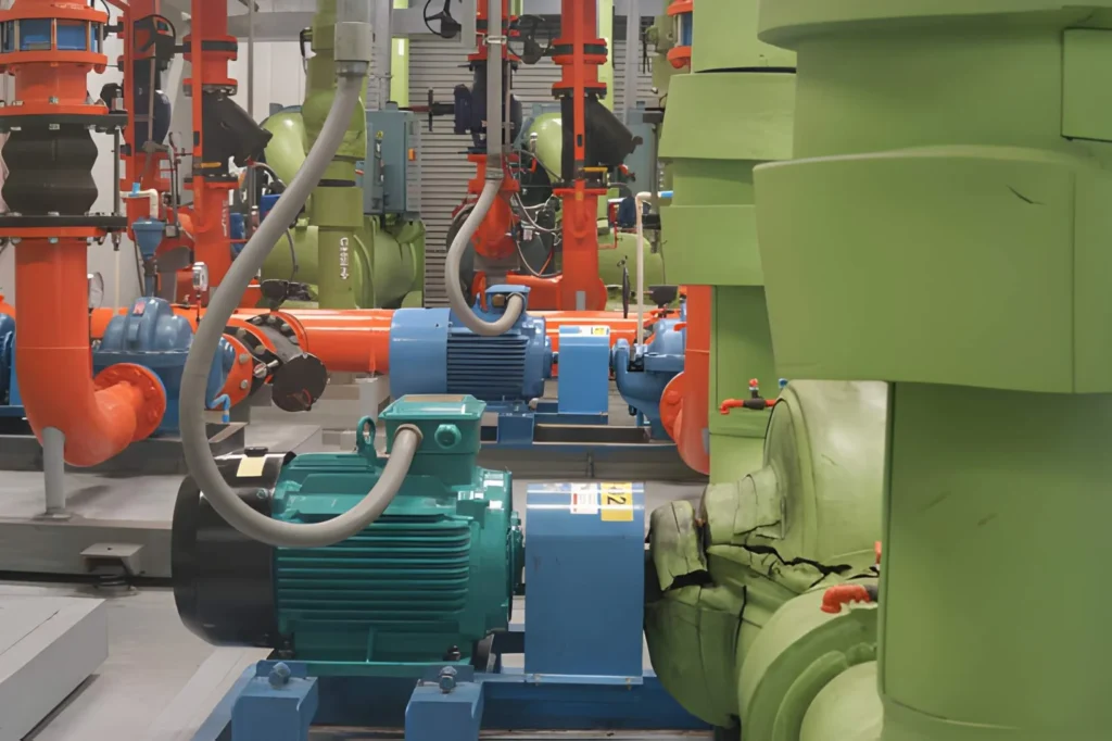
Pumps
Common issues: clogging, valve misoperation, wear increasing torque demand, loss of prime (underload).
Useful functions:
- thermal overload
- phase loss/imbalance
- underload/undercurrent (where applicable)
Conveyors / material handling
Common issues: jams, misalignment, friction spikes, intermittent stalls.
Useful functions:
- stall/locked-rotor supervision
- faster overload response (when justified)
- event logging to diagnose recurring trips
Compressors / high inertia loads
Common issues: long start, high torque, heat accumulation, frequent cycling.
Useful functions:
- appropriate trip class / tuned thermal model
- start-time supervision
- thermal capacity tracking (avoid “reset and re-trip” loops)
| Application | Typical overload driver | Protection priority | Recommended device tier |
|---|---|---|---|
| Pumps | Blockage / wear | Thermal + imbalance + (optional underload) | Thermal / Electronic |
| Conveyors | Jam / stall | Stall supervision + fast abnormal detection | Electronic / MPR |
| Compressors | Long start / cycling | Trip dynamics + thermal tracking | Electronic / MPR |
Subtle CTA: If you share the motor nameplate data, start method, measured start time, and load type, we can help you select and set electric motor overload protection that reduces nuisance trips while keeping thermal margins defensible—useful if you’re standardizing across a facility or redesigning an MCC lineup.
Commissioning: verify settings with measurable tests, not hope
The fastest way to turn “overload protection” into engineered electric motor overload protection is commissioning discipline:
- Measure real operating current under normal and worst-case process conditions
- Record cold and hot start times and compare to your trip behavior assumptions
- Check phase imbalance under load and validate detection thresholds
- Validate reset and restart behavior against safety requirements
- Review event logs (if available) to confirm trip cause is explainable
If you can’t link a trip to a plausible thermal or electrical cause, treat that as a design defect—not a “weird motor mood.”
Conclusion
Professional electric motor overload protection is thermal engineering, not just current limiting. When you choose protection based on motor heating behavior, start dynamics, and coordination with short-circuit devices, you reduce nuisance trips and protect insulation life in a defensible way. The best setups combine the right device tier (thermal, electronic, or MPR), correct trip dynamics, and commissioning data that proves the settings match reality. Do that, and your motors stop failing “mysteriously”—because you’ve built protection that understands what actually kills them: heat over time.
FAQ
Can an electric power meter detect motor overload?
It can indicate overload risk by showing sustained current or kW rising over time, but it doesn’t replace electric motor overload protection. Think of a meter as a diagnostic and trending tool.
What power meter readings suggest an overload problem?
Look for sustained current above baseline, increasing kW at the same throughput, worsening power factor, and growing phase imbalance. These often point to mechanical degradation or process changes driving overload.
Do I still need overload protection if I have a power meter?
Yes. A power meter measures; electric motor overload protection trips to prevent damage. Measurement without protective action doesn’t stop overheating.
Can power meters help set overload relay values?
They can help validate your assumptions by providing real load current and start profiles. Final settings should still align with motor thermal limits and coordination requirements.
Are power meters accurate on VFD outputs?
Some are, but many require true-RMS and harmonic-capable measurement. Even then, use the meter for trends and verification; keep electric motor overload protection aligned with the motor’s thermal reality.