In modern electrical systems, fuses and circuit breakers are indispensable protection devices.

Their main function is to prevent damage to circuits due to overloads or short circuits, thus ensuring the safe operation of equipment. The symbols used in electrical drawings are important tools for understanding these devices.

Based on the fuse and circuit breakers symbols shown in the pictures, this article will analyze their types, functions and application scenarios in detail to help readers better understand the design and use of electrical protection equipment.

Explanation of fuse symbols

Fuse is a simple and efficient circuit protection device whose symbols vary under different standards. Below are the fuse symbols and their functional classifications shown in the pictures:

Basic fuse symbols

    • IEC System: The rectangle indicates the basic fuse, which conforms to the International Electrotechnical Commission (IEC) standard.
    • IEEE/ANSI System: Symbols with arcs or other markings are used, conforming to the specifications of the American National Standards Institute (ANSI) and the Institute of Electrical and Electronic Engineers (IEEE).

    Special Types of Fuses

      • Thermal Fuse: Used to automatically shut off a circuit when the temperature is too high, commonly found in household appliances.

      Fast-Blow Fuse and Slow-Blow Fuse:

      • Fast-blow fuses are used in sensitive equipment to quickly cut off overload currents.
      • Slow-blow fuses are used for equipment with high instantaneous currents at start-up, e.g. motors.

      Fuses with additional functions

        • Fuse with Striker: triggers a mechanical indication or alarm in the event of a blown fuse.
        • Fuse with Alarm Contact: Suitable for remote monitoring systems to signal the occurrence of a fault.

        Specialized fuses for high voltage

          • Oil Fuse: Used in high voltage systems to provide higher insulation and arc extinguishing capability.
          Fuse-Circuit-Breakers-Protection-Symbols

          Circuit Breakers Symbol Explanation

          A circuit breaker is a reusable protective device with more complex functions for a variety of electrical systems. Below are the main types and their symbols explained in the picture:

          Ordinary circuit breakers

            • The standard symbol indicates its basic function: to cut off the current in case of overload or short-circuit.

            Molded Case and Drawout Circuit Breakers

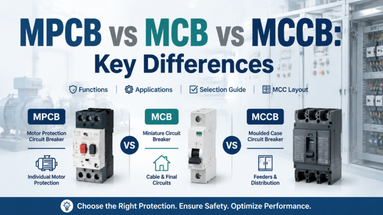
              • Molded Case Circuit Breaker (MCCB): commonly used in small and medium-sized industrial equipment, with fixed installation characteristics.
              • Drawout Circuit Breaker (Drawout Circuit Breakers): easy to maintain, can be pulled out directly from the distribution cabinet.

              Multipole circuit breaker

                Single-pole, double-pole, three-pole and other multi-pole design for single-phase and three-phase systems:

                • Single-pole: for simple single-phase loads.
                • Three-pole: widely used in industrial three-phase power supply system.

                Network Protector

                • Network Protector: Designed for complex power supply networks to prevent reverse power flow.

                Other Protective Device Symbols

                In addition to fuses and circuit breakers, other important protective devices and their symbols are shown in the picture:

                Lightning protection devices

                • Lightning rods and arresters: protect buildings and equipment from lightning damage.

                Spark Gap

                • Function: To limit overvoltage, commonly found in high voltage transmission and distribution systems.

                Thermal Switches and Thermostats

                • Thermal switches and thermostatic controls are widely used in scenarios that require temperature monitoring, such as heating equipment.

                Conclusion

                By analyzing the fuse and circuit breaker symbols in the picture, it can be seen that these symbols not only help engineers to quickly understand electrical diagrams, but also guide the selection and configuration of equipment in actual operation.

                Familiarity with these symbols is essential for improving design efficiency and ensuring system safety.

                Appendice

                Class of symbolsExample SymbolsApplication scenario
                FuseIEC/IEEE SymbolsOverload protection for domestic and industrial equipment
                Thermal fuseThermal Fuse SymbolTemperature sensitive equipment
                InterrupterUnipolar/multipolar/withdrawableSwitchboards and industrial power supply systems
                lightning protectionLightning rods/gapsPreventing damage from lightning strikes
                Spark gapSpark Gap SymbolHigh voltage transmission and distribution lines

                Previous Post

                Waterproof Electrical Junction Box

                Next Post

                Motor Protection Circuit Breaker Electrical Symbols Explained

                Related Posts

                +86-13616648938 Phone zhengkan@zk-ele.com E-mail