In modern industrial automation and power distribution systems, electrical symbols are like a universal language among engineers, carrying complex technical information and functional instructions.
In the case of Motor Protective Circuit Breakers (MPCBs), understanding the electrical symbols is not only the basis for designing the electrical system, but also the key to ensuring the safe operation of the equipment.
A standardized electrical symbol system can break through the language barrier, enabling engineers to communicate globally without barriers, greatly improving design efficiency and system reliability.
According to the statistics of the International Electrotechnical Commission (IEC), more than 85% of electrical accidents can be traced back to incorrect interpretation of electrical drawings or improper selection of electrical components, and these problems often stem from a deviation in the understanding of electrical symbols.
Therefore, mastering MPCB’s knowledge of electrical symbols is not only a manifestation of professional ability, but also a necessary condition for system safety.
Basic Functions of Motor Protection Circuit Breaker
As an indispensable protection device in modern industrial systems, the motor protection circuit breaker integrates multiple protection functions in one:
- Short-circuit protection: cut off the fault current in milliseconds response time to prevent equipment damage and fire risk
- Overload protection: according to the preset current-time characteristic curve, disconnect the circuit when the motor is overloaded
- Phase loss protection: detect the phase sequence and integrity of the three-phase power supply, prevent the motor from burning due to phase loss operation Phase loss protection: detects the phase sequence and integrity of the three-phase power supply, preventing the motor from burning up due to phase loss
- Undervoltage protection: monitors the voltage fluctuation of the power grid, avoiding overheating of the motor due to low voltage
- Manual operation function: provides an interface for on-site operation, which makes it easy for maintenance personnel to isolate the equipment
MPCBs have been widely used in pumping systems, HVAC equipment, production line conveyor belts, and various types of industrial machinery.
For example, in a 75kW water pump system, a suitable MPCB not only protects the wiring in the event of a short-circuit, but also sets the appropriate overload protection parameters according to the starting characteristics of the pump, avoiding the damage caused by frequent starts and stops.
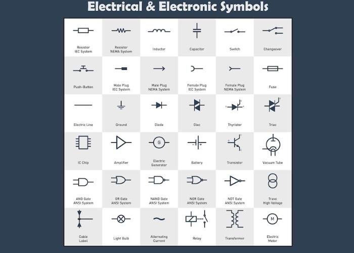
Explanation of electrical symbols related to MPCB
Comparison of basic symbols with international standards
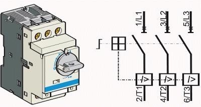
IEC Standard Symbols (International Electrotechnical Commission):

Where the box represents the main body of the circuit breaker, the slash indicates the automatic release function, and the M mark is designed for motor protection.
ANSI Standard Symbols (American National Standards Institute):

The two-line symbol indicates a circuit breaker with a thermo-magnetic disconnect function.
Chinese National Standard (GB) Symbol:

Similar to the IEC standard, but with differences in detail representation.
Explanation of Auxiliary Function Symbols
In addition to the basic protection functions, modern MPCBs are equipped with a variety of auxiliary functions, each of which is indicated by a special symbol:
- Auxiliary Contact Symbol: —[NO/NC]— Indicates a normally open/closed auxiliary contact, used for condition monitoring and interlocking control
- Alarm Contact Symbol: ––[AL]— Indicates an alarm output contact, used for remote monitoring
- Voltage Detent Symbol: —[UV/OV]— Indicates undervoltage/overvoltage protection function UV/OV]— Indicates under/over voltage protection function
- Shunt release symbol: ––[ST]— Indicates remote control disconnect function
Withholding Characteristics Symbols
The withholding characteristics of MPCBs are usually indicated in the symbols by letter codes:
- Class A: Standard withholding characteristics, applicable to general loads
- Class B: 3-5In withholding current, applicable to resistive loads
- Class C: 5-10In withholding current, applicable to slightly inductive loads Class D: 5-10In withholding current, applicable to slightly inductive loads Class C: 5-10In tripping current for slightly inductive loads
- Class D: 10-20In tripping current for strongly inductive loads, e.g. motor starting
- Class MA: Tripping characteristic designed for motor starting
The relationship between electrical symbols and product selection
Knowledge of MPCB’s electrical symbols can significantly improve the accuracy of product selection. In the actual project, through the correct interpretation of the electrical symbols, engineers can quickly determine:
- Protection range and level: the letter code in the symbol (such as “M”) indicates that the circuit breaker is specially designed for motor protection, with a specific time-current characteristics
- Current adjustment range: the symbols are usually labeled next to the symbols in the electrical diagrams, such as “0.63-1A” value, which indicates that the overload protection adjustable range
- Rated breaking capacity: the “kA” value after the symbol (such as “50kA”) indicates that the overload protection can be adjusted. Rated breaking capacity: the “kA” value after the symbol (e.g. “50kA”) indicates the maximum short-circuit current that can be safely cut off by the circuit breaker
- Auxiliary function: through the auxiliary symbols, it can be recognized whether the circuit breaker has special functions such as alarm output, under-voltage protection, etc.
Technical Details: Tripping Classes and Application Scenarios
Symbolization and Technical Meaning of Tripping Classes
The tripping classes of MPCBs are usually indicated by a number next to the symbol, and the most common ones are Class 10, Class 20 and Class 30:
- Class 10 (Class 10): The symbol “10” means that the circuit breaker will be tripped within 10 seconds at 7.2 times the rated current
- Class 20 (Class 20): The symbol “20” means that the circuit breaker will be tripped within 20 seconds at 7.2 times the rated current Class 30 (Class 30): The symbol “20” means that the circuit breaker will be tripped within 20 seconds at 7.2 times the rated current Class 20 (20): The symbol “20” indicates that the circuit breaker will release within 20 seconds at 7.2 times the rated current.
- Class 30 (30): The symbol “30” indicates that the circuit breaker will release within 30 seconds at 7.2 times the rated current.
Selection of release level for different application scenarios
It is important to select the appropriate release level according to the starting characteristics of the motor and the loading conditions.
- For light load fast start applications: Select Class 10 for small water pumps. Class 10 for small pumps, fans, etc. with low starting current and short starting time
- Medium load applications: Class 20 for compressors, medium pumps, etc. with long starting time
- Heavy load hard starting applications: Class 30 for high inertia loads, heavy pulverizers, etc. with long starting time
Conclusion: The Importance of Choosing the Right MPCB and Symbol Understanding
The electrical symbols of motor protection circuit breakers carry a wealth of technical information, and a proper understanding of these symbols not only improves the accuracy of electrical system design, but also significantly improves troubleshooting and maintenance efficiency. For industrial users, mastering the knowledge of these symbols means being able to:
- Accurate selection: choose the most suitable protection device according to the load characteristics, avoiding under-protection or over-protection
- Enhance safety: accurately understand the meaning of the symbols to ensure that the correct configuration of each protection function, reducing safety risks
- Reduce maintenance costs: quickly identify the structure of the system through the symbols to shorten the time of troubleshooting and reduce the loss of downtime
- Optimize the performance of the system : Utilizing symbolic information to rationally configure system parameters and improve equipment operating efficiency
When selecting motor protection circuit breakers, in addition to basic current specifications, engineers are advised to pay special attention to key parameters indicated by symbols such as the stripping characteristics, breaking capacity and auxiliary functions, which are details that often determine the reliability and applicability of the protection system.