Icu vs Ics in MCCBs: How to Read Breaking Capacity Ratings
Icu vs Ics in MCCBs: what each short-circuit rating tells a buyer, why they differ, and which datasheet values to check before specifying a breaker.
Read More
Choosing from a list of electrical distribution box sizes looks simple until the breakers, terminals, cables and mounting hardware have to fit inside. A box that matches the width of the devices on paper may still leave no room to terminate conductors, close the cover or service the installation later.
The practical way to size a distribution box is to start with the complete component layout, then check usable internal width, height and depth. Only after that should you compare the outside dimensions in a product listing. This guide covers the measurements buyers need before selecting a standard or custom plastic enclosure.
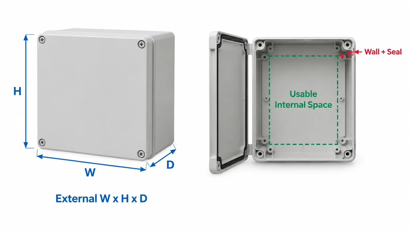
There is no one size that fits every six-circuit, twelve-circuit or industrial installation. The physical space depends on the device mix, pole count, terminals, cable sizes and mounting method. Two boxes with similar outside measurements can have different usable space because of wall thickness, seals, mounting bosses, internal plates and cover shape.
Product listings may use width × height × depth or height × width × depth. Check the order in the drawing. Also establish whether the figures describe external dimensions, clear internal dimensions or the mounting plate. A dimensioned drawing is more useful for panel planning than a nominal box size alone.
Record every item planned for the enclosure:
A module count is a useful starting point for a DIN-rail layout, but it does not describe the entire box. Terminals and wiring may take substantial space. Use the manufacturers’ actual component drawings.
Draw the DIN rails or mounting plate and place each device at its real dimensions. Add room for conductors to enter, bend, terminate and be identified. A layout that technically fits but cannot be wired or serviced is too small.
Look beyond one row of breakers. With several rails, check access to terminals and the routes between rows. Show any partition, busbar cover or accessory in the drawing. Cable-entry locations can change the layout: a gland placed directly behind a device may be difficult to terminate even when the box is otherwise large enough.
For waterproof installations, plan gland and conduit locations before making openings. Confirm that the installed fittings and modifications maintain the required environmental protection.
Depth is easily overlooked. The enclosure needs space for the mounting structure, the deepest device, its terminals and cables, plus any projection from the inside of the door. A transparent cover makes inspection easier but does not tell you how much usable depth is available.
Use a side-view drawing or sample if the assembly includes a tall breaker, socket, cable bend or door-mounted accessory. Confirm the door can close without touching components or compressing the wiring. Follow each device manufacturer’s clearance and installation instructions.
Several devices inside a sealed box can generate heat. A larger enclosure alone does not guarantee acceptable internal temperatures. Assess the actual equipment losses, ambient conditions, required spacing and thermal-management needs of the complete assembly.
Outdoor and dusty locations also require a suitable enclosure and properly installed cable entries. An IP rating describes a protection level under specified conditions; consider it alongside enclosure material, mounting and maintenance access. ZKELE has a separate IP65 vs IP66 vs IP67 guide for comparing these ratings.
ZKELE lists six nominal dimensions for its IP67 waterproof plastic distribution box:
| Listed size | What a buyer should verify |
|---|---|
| 340 × 220 × 160 mm | Usable mounting area and component termination space |
| 400 × 300 × 160 mm | Width for devices and wiring routes |
| 460 × 270 × 160 mm | Whether the wider layout suits the proposed rail arrangement |
| 520 × 300 × 160 mm | Cable-entry positions and service access |
| 540 × 360 × 180 mm | Depth, cable bends and cover clearance |
| 680 × 500 × 200 mm | Mounting support and thermal behavior of the finished assembly |
These are published product dimensions, not a circuit-capacity chart. Do not assume that a particular breaker count fits one size. Check the dimension order and request a drawing showing usable internal space and mounting positions before ordering.
Suppose a contractor needs an outdoor box for several protective devices, a main isolator, neutral and earth terminals, and multiple outgoing cables. First place the exact devices on a proposed DIN rail or mounting plate using their datasheets. Mark cable entries and trace how each conductor reaches its terminal.
Next check three views: front view for width and height, side view for depth and cover clearance, and the cable-entry area for gland spacing. Keep the access required for wiring, inspection and replacement. Compare the assembly with the supplier’s usable internal dimensions. If the terminals are crowded or the proposed holes interfere with the seal, change the layout or select another box.
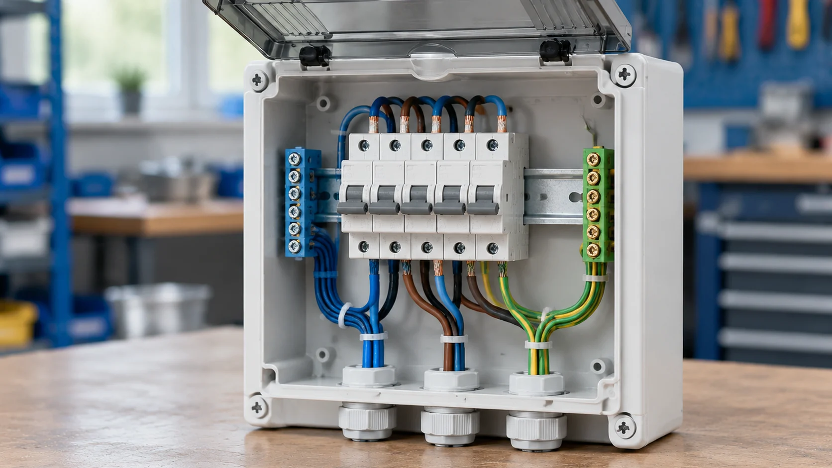
This process is more reliable than choosing only by circuit count. It also gives the supplier enough detail to recommend a standard model or assess a custom configuration.
For an accurate recommendation, provide:
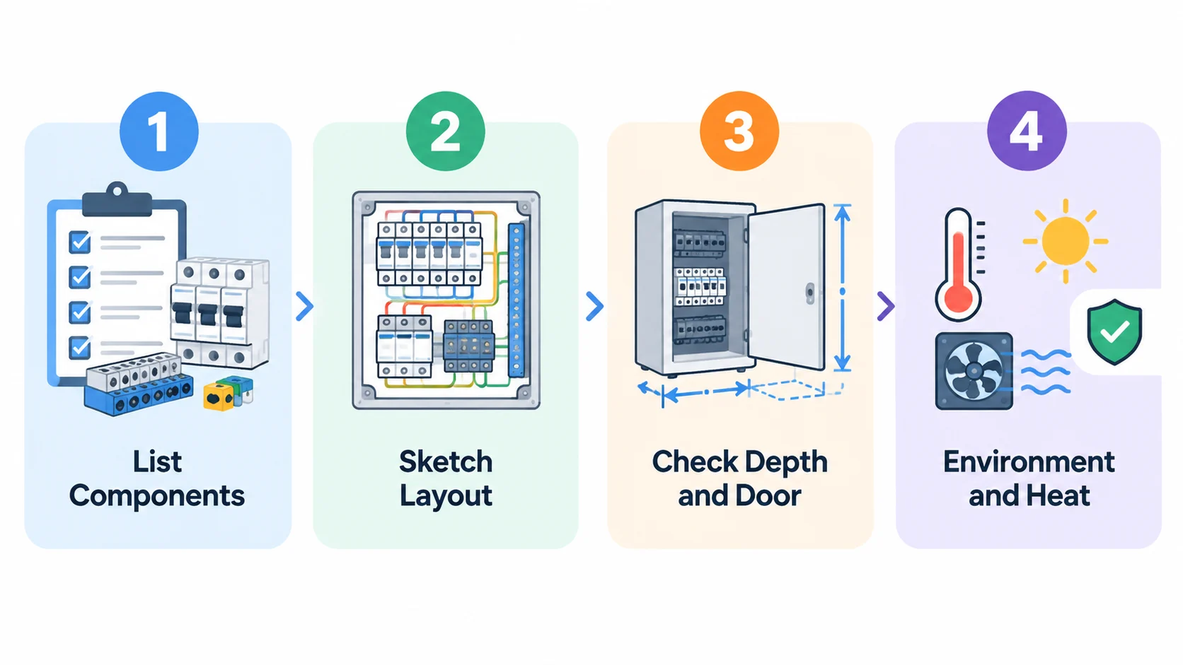
ZKELE lists enclosure size, DIN-rail design, terminal layout and other structural options among its plastic distribution box customization capabilities. Sending a drawing makes it easier to check the proposed configuration before production.
Breaker count alone is insufficient. Check pole widths, rails, terminal blocks, conductor routes, usable internal dimensions, device clearances and any planned expansion.
Not necessarily. Ask whether the figures refer to external dimensions, clear internal dimensions or the mounting plate. Request a model drawing before using them to confirm a fit.
Choose a box that accommodates the finished assembly and meets the project requirements. A larger size can improve access, but wall space, mounting, cost and thermal conditions also matter.
Plan the location and fittings with the supplier. The completed installation, including its cable entries and modifications, must meet the environmental protection required by the project.
When comparing electrical distribution box sizes, start with installed components and cable routes. Confirm usable width, height, depth and door clearance, then select the external size. Browse ZKELE’s plastic distribution box range or send a component list and drawing for a standard or custom enclosure recommendation.