3-Phase Motor Full Load Current Chart (400 V / 415 V)
Full load current chart for standard 3-phase motors, 0.37-75 kW at 400 V and 415 V - with overload setting and the recommended MPCB model for each rating.
Read More
Choosing an MPCB takes two steps: pick the right size, then set the dial. The rating chart below lists every GV2-M model with its rated current, adjustable setting range and breaking capacity; the selection chart then maps common motor ratings in kW and HP to a specific model and starting dial setting.
This guide covers the full rating table, how to read In, Icu and Ics, how to match a model to a motor nameplate, how the setting range is chosen, and how to verify the setting after commissioning.
Every GV2-M model is identified by an adjustable setting range rather than a single fixed current, so the thermal trip can be trimmed to the exact motor FLA. The table below lists the full ladder of sizes, from 0.10 A up to 32 A. Use the Model and Setting range columns to pick a device, then check the Icu / Ics column that matches your network voltage against the prospective fault current at the installation point.
| Model | Rated current In (A) | Setting range (A) | 230–240 V Icu / Ics (kA) | 400–415 V Icu / Ics (kA) | 440 V Icu / Ics (kA) | 500 V Icu / Ics (kA) | 690 V Icu / Ics (kA) |
|---|---|---|---|---|---|---|---|
| GV2M01C | 0.16 | 0.10–0.16 | 100 / 100 | 100 / 100 | 100 / 100 | 100 / 100 | 100 / 100 |
| GV2M02C | 0.25 | 0.16–0.25 | 100 / 100 | 100 / 100 | 100 / 100 | 100 / 100 | 100 / 100 |
| GV2M03C | 0.4 | 0.25–0.40 | 100 / 100 | 100 / 100 | 100 / 100 | 100 / 100 | 100 / 100 |
| GV2M04C | 0.63 | 0.40–0.63 | 100 / 100 | 100 / 100 | 100 / 100 | 100 / 100 | 100 / 100 |
| GV2M05C | 1 | 0.63–1.00 | 100 / 100 | 100 / 100 | 100 / 100 | 100 / 100 | 100 / 100 |
| GV2M06C | 1.6 | 1.00–1.60 | 100 / 100 | 100 / 100 | 100 / 100 | 100 / 100 | 100 / 100 |
| GV2M07C | 2.5 | 1.60–2.50 | 100 / 100 | 100 / 100 | 100 / 100 | 100 / 100 | 3 / 2.25 |
| GV2M08C | 4 | 2.50–4.00 | 100 / 100 | 100 / 100 | 100 / 100 | 100 / 100 | 3 / 2.25 |
| GV2M10C | 6.3 | 4.00–6.30 | 100 / 100 | 100 / 100 | 50 / 50 | 50 / 50 | 3 / 2.25 |
| GV2M14C | 10 | 6.00–10.00 | 100 / 100 | 100 / 100 | 15 / 15 | 10 / 10 | 3 / 2.25 |
| GV2M18C | 14 | 9.00–14.00 | 100 / 100 | 15 / 7.5 | 8 / 4 | 6 / 4.5 | 3 / 2.25 |
| GV2M20C | 18 | 13.00–18.00 | 100 / 100 | 15 / 7.5 | 8 / 4 | 6 / 4.5 | 3 / 2.25 |
| GV2M21C | 23 | 17.00–23.00 | 50 / 50 | 15 / 6 | 6 / 3 | 4 / 3 | 3 / 2.25 |
| GV2M22C | 25 | 20.00–25.00 | 50 / 50 | 15 / 6 | 6 / 3 | 4 / 3 | 3 / 2.25 |
| GV2M32C | 32 | 24.00–32.00 | 50 / 50 | 10 / 5 | 6 / 3 | 4 / 3 | 3 / 2.25 |
In is the rated current, the top of the setting range. Icu is the rated ultimate short-circuit breaking capacity and Ics is the rated service short-circuit breaking capacity, normally expressed as a percentage of Icu. Breaking capacity falls as system voltage rises, so always read the column for your own voltage — a device that is comfortable on a 400 V system may need checking on 690 V.
Series data for the GV2-M frame: rated insulation voltage Ui 690 V, rated operational voltage Ue 230/240–690 V, rated impulse withstand Uimp 8 kV, rated frequency 50/60 Hz, frame rated current Inm 32 A, arc distance 40 mm, conforming to IEC 60947-4-1. The figures are quoted from the GV2-M series datasheet; confirm them against the current datasheet for your voltage and prospective fault level before specifying.
Motors above the GV2-M ceiling need the larger frame. The GV3-M series covers a 40–63 A setting range using the same thermal-magnetic principle: adjustable thermal overload for the running current, a fixed magnetic trip for short circuit, and manual switching. It is the right choice for larger pumps, compressors and conveyor drives whose full-load current runs above 32 A.
Follow these three steps every time you set an MPCB for a three-phase motor:
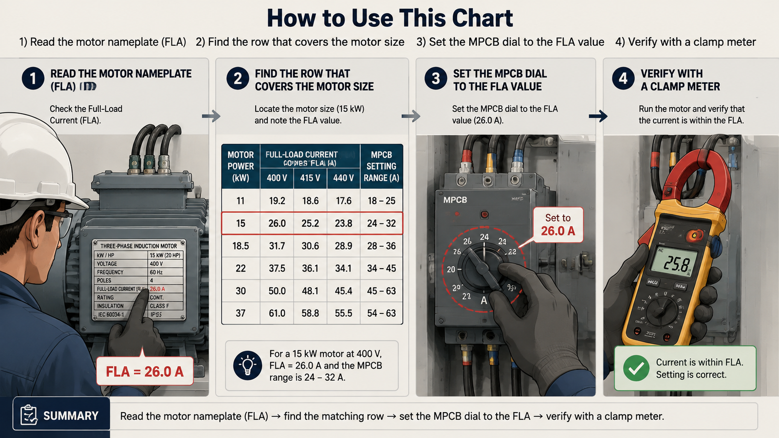
The table gives typical full-load currents for standard 400 V three-phase induction motors. Values vary with motor design, efficiency, and power factor — always use the nameplate FLA as the final reference. Ranges follow the GV2-M (0.16–32 A) and GV3-M (40–63 A) series.
| Motor Power (kW / HP) | Recommended Model | Typical FLA @ 400 V (A) | Recommended MPCB Range (A) | Starting Dial Setting (A) |
|---|---|---|---|---|
| 0.75 kW (1 HP) | 1.4–1.8 | GV2M07C | 1.6–2.5 | 1.8–2.0 |
| 1.5 kW (2 HP) | 2.8–3.4 | GV2M08C | 2.5–4 | 3.2–3.8 |
| 2.2 kW (3 HP) | 4.2–4.8 | GV2M10C | 4–6.3 | 4.8–5.5 |
| 3.7 kW (5 HP) | 7.0–7.6 | GV2M14C | 6.3–10 | 8.0–8.7 |
| 5.5 kW (7.5 HP) | 10.4–11 | GV2M18C | 9–14 | 12–12.6 |
| 7.5 kW (10 HP) | 14.2–14.8 | GV2M20C | 13–18 | 16–17 |
| 11 kW (15 HP) | 20.8–21 | GV2M22C | 20–25 | 24 |
| 15 kW (20 HP) | 27–28.3 | GV2M32C | 24–32 | 30–32 |
| 22 kW (30 HP) | 40–41.6 | GV3-M 40–63 A | 40–63 (GV3-M) | 45–48 |
If your motor’s FLA falls between two rows, choose the range that places the current closest to its midpoint. For example, a 10.5 A motor fits the 9–14 A range better than 13–18 A. For the full selection procedure behind this table, see how to select an MPCB for a 3-phase motor.
For most IEC-type MPCBs, the initial thermal setting is the motor’s nameplate current. The dial value is the reference around which the thermal element evaluates overload — set it higher than the motor rating and protection acts too late; set it lower and the motor trips unnecessarily during normal running.
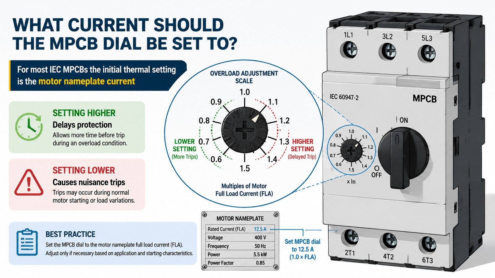
The range selection matters as much as the dial setting. An MPCB’s adjustable range must cover the motor FLA comfortably — ideally with the FLA near the middle of the dial — so there is margin for fine-tuning during commissioning.
For example, the GV2-M manual starter and protector series covers 0.16–32 A in standard ranges (1.6–2.5 A, 2.5–4 A, 4–6.3 A, 6.3–10 A, 9–14 A, 13–18 A, 20–25 A, 24–32 A), while the GV3-M series covers 40–63 A for larger motors. A motor drawing 12.4 A should use the 9–14 A range set to 12.4 A — not a 13–18 A unit set at its minimum, and not a 17–23 A unit that cannot protect the windings from a sustained overload.
Voltage. The chart is based on 400 V. At 415 V the full-load current is roughly 4% lower, and at 380 V roughly 5% higher, because current is inversely proportional to voltage for the same power. In practice the recommended ranges in the table still cover these values; only the dial setting changes slightly.
Starting method. A direct-on-line (DOL) start draws 6–8 times FLA briefly, which the magnetic trip must tolerate. Motors on soft starters or variable frequency drives (VFDs) start with lower current, so nuisance trips at startup are less likely. If the MPCB trips during every start, check the starting time against the trip-class curve before changing the thermal setting — see electric motor overload protection for the background.
After commissioning, measure each phase current with a clamp meter under normal load. All three phases should be balanced and within the motor rating. If a phase current runs consistently above the setting under normal load, the motor may be overloaded or the setting may need to follow the manufacturer’s guidance for the service factor. If the motor trips at startup but runs fine once started, revisit the trip class and starting current rather than raising the dial past the nameplate value.
The range is the adjustable window of the device (e.g. 9–14 A). The dial setting is the value you choose inside that window — normally the motor’s full-load current. Both are part of correct protection.
No. Setting above the motor rating means the thermal element only acts at a current the motor cannot safely sustain. Fix the root cause of tripping (trip class, starting current, or range) instead.
Usually not. For most IEC MPCBs start at the nameplate FLA; many devices already include the overload margin in their design. Some motor protection relays use 1.05–1.2 × rated current — follow the specific device manual and the motor service factor. This differs from the role of a separate thermal overload relay — see MPCB vs thermal overload relay.
Choose the range that places the FLA closest to its midpoint. For a 14 A motor, the 13–18 A range is a better fit than 20–25 A.
An MCB has a fixed trip rating and curve for general wiring. An MPCB has an adjustable thermal dial plus magnetic and phase-loss protection matched to motor starting behavior — see the MPCB vs MCB vs MCCB comparison.
Our motor protection circuit breakers cover 0.10 A to 63 A in two frames: the GV2-M series spans 0.10–32 A across 15 models from GV2M01C to GV2M32C, and the GV3-M series covers 40–63 A. Models are assigned by setting range rather than motor size, so a 4 kW and a 5.5 kW motor can land on the same device.
Icu is the ultimate breaking capacity — the device clears the fault but may need inspection or replacement afterwards. Ics is the service breaking capacity — the device clears the fault and stays in service. Ics is quoted as a percentage of Icu, and it is the figure that matters when the panel has to keep running after a fault.
Read the motor nameplate FLA first, then take the model whose setting range contains that value nearest to its midpoint. The selection chart above does this for common 400 V motors in kW and HP, but always verify against the nameplate — two motors of the same power rating can differ in current.
A 22 kW (30 HP) 400 V motor draws roughly 40–42 A, which is above the 32 A GV2-M ceiling, so it needs the GV3-M 40–63 A frame with the dial set near 45 A.
Both tables on this page are also available as a single-page PDF for your panel documentation, submittal package or maintenance file: MPCB rating and selection chart (PDF, 1 page). If you need the figures for a voltage or fault level that is not listed, send us the motor nameplate data together with the available fault current and we will confirm the model, the setting range and the Icu/Ics values for your application.
Selecting and setting an MPCB for a three-phase motor is straightforward once the rating and selection charts are in front of you: read the nameplate FLA, find the model whose setting range covers it near the midpoint, check Icu against the prospective fault current at your voltage, set the dial to the FLA, then verify with a clamp meter. Avoid the habit of raising the setting to silence nuisance trips — correct the range or trip class instead.
Need the right MPCB for your motor? Browse the MPCB product range or the GV2-M manual motor starter range, or contact us with your motor nameplate data and we will confirm the correct range and dial setting.