3-Phase Motor Full Load Current Chart (400 V / 415 V)
Full load current chart for standard 3-phase motors, 0.37-75 kW at 400 V and 415 V - with overload setting and the recommended MPCB model for each rating.
Read More
Selecting a motor protection circuit breaker (MPCB) for a three-phase motor comes down to one rule: match the device’s adjustable current range to the motor’s nameplate full-load current, then verify short-circuit capacity and starting behavior. Read the nameplate, choose a range that covers the motor current near its midpoint, set the overload to roughly 1.15 times the full-load amperage (FLA), and confirm the breaking capacity exceeds the available fault current at the installation point.
This guide walks through the complete selection process for IEC-style MPCBs such as the GV2-M and GV3-M series, with a sizing table for common 400 V motors, the mistakes that cause most field problems, and a short FAQ.
A motor protection circuit breaker combines overload, short-circuit, and phase-loss protection in a single device designed around motor starting behavior. Unlike a standard MCB with a fixed trip curve, an MPCB has an adjustable thermal overload setting and a magnetic short-circuit trip tuned to ride through the inrush current a motor draws during startup.
Three-phase motors are expensive to repair and their windings fail quickly when they overheat. An MPCB protects against the three most common failure causes in one compact unit:
For a deeper look at how MPCBs differ from alternative protection, see our comparison of MPCB vs MCCB and MPCB vs thermal overload relay.
Selection starts on the motor nameplate, not in the breaker catalog. Record these values before anything else:
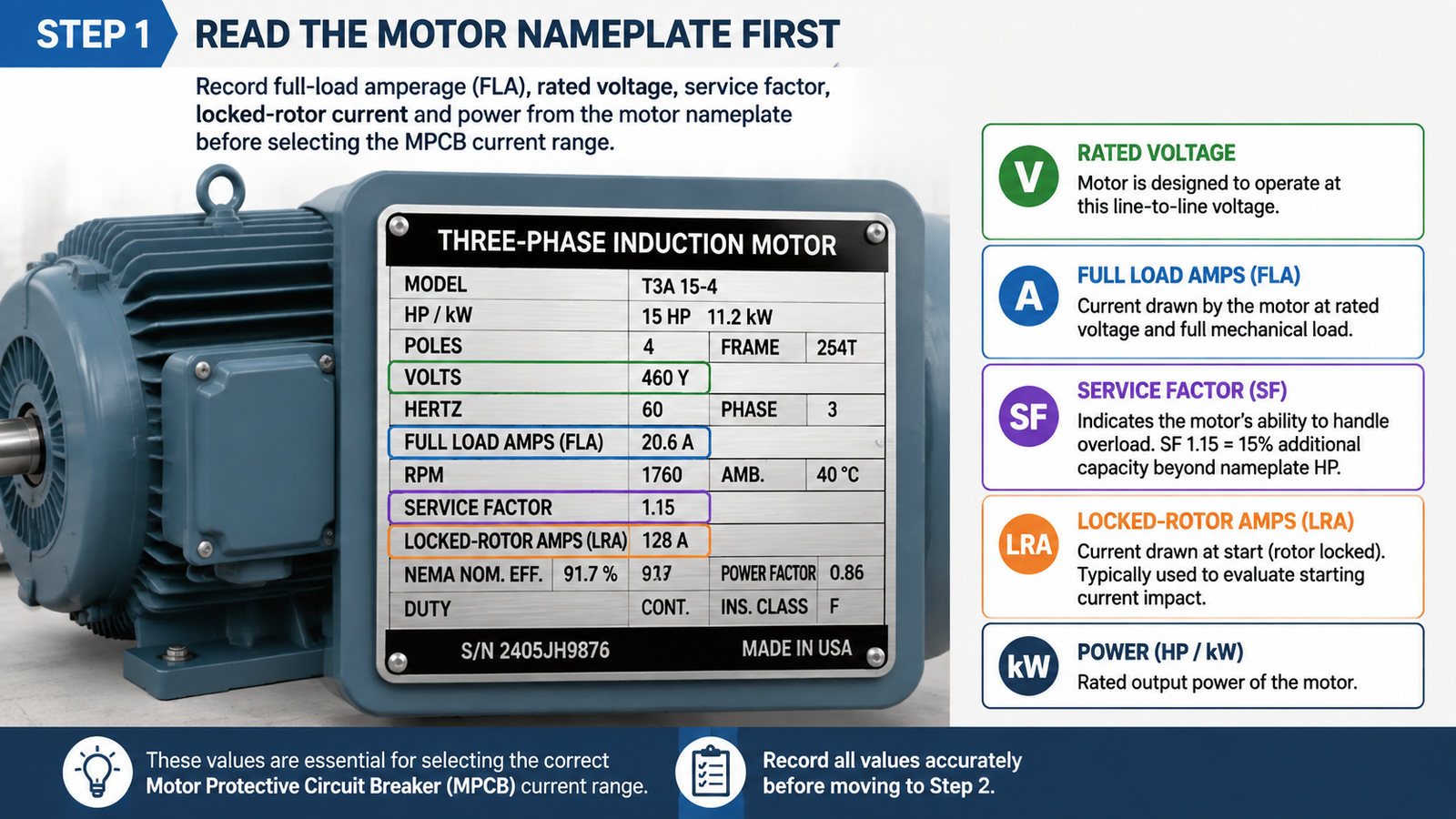
If the nameplate is unreadable, measure the running current with a clamp meter under normal load and treat that as a starting reference — but replace the motor data before finalizing the setting.
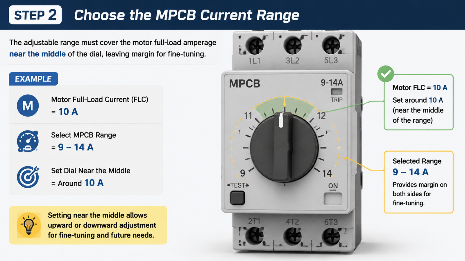
The most common selection error is picking a breaker by motor power (kW or HP) instead of by current. An MPCB’s adjustable range must cover the motor FLA, and ideally place the FLA near the middle of the dial rather than at either extreme. This leaves room for fine-tuning during commissioning and avoids operating at the edge of the thermal band.
As a practical rule, the overload setting is usually started at 1.15 × FLA for motors with service factor 1.0 (or at FLA for SF 1.15 motors), then adjusted after observing actual running current. So if a motor draws 10 A, choose an MPCB range such as 9–14 A and set the dial around 11.5 A — not a 16 A unit set at its minimum.
For example, the GV2-M manual starter and protector series offers ranges from 0.16 A up to 32 A (e.g. 1.6–2.5 A, 2.5–4 A, 4–6.3 A, 6.3–10 A, 9–14 A, 13–18 A, 20–25 A, 24–32 A), while the GV3-M series covers 40–63 A for larger motors.
After installing the MPCB, set the thermal dial to the motor FLA (or 1.15 × FLA per the rule above) and verify with a running-current measurement. The trip class controls how long the overload element tolerates starting current before tripping:
If the MPCB trips during normal starting, the current setting may be too low or the trip class too fast — do not simply raise the setting past the motor rating, or you lose overload protection. Check the starting time against the trip-class curve first.
The MPCB’s rated breaking capacity must equal or exceed the prospective short-circuit current (PSCC) available at its point of installation. If the breaker is undersized for the fault level, it may not clear a severe short circuit safely, and the enclosure or downstream equipment can be damaged.
For industrial starters built with a contactor, also check the manufacturer’s coordination table for Type 1 or Type 2 coordination per IEC 60947-4-1. Type 2 coordination (no significant damage to the starter after a fault) is preferred in critical applications because it reduces downtime and replacement cost. Confirm the PSCC with your utility or a short-circuit study rather than guessing.
Starting method. A direct-on-line (DOL) start draws roughly 6–8 times FLA, so the magnetic trip must be set above this inrush (typically 8–14 × FLA on adjustable MPCBs) to avoid nuisance tripping. Motors started with soft starters or variable frequency drives (VFDs) have lower starting current and can use lower magnetic settings.
Ambient temperature. Thermal overload elements respond to heat. In hot, poorly ventilated enclosures the effective trip point shifts, so either derate the setting or choose a breaker rated for the environment. For outdoor or washdown areas, a waterproof enclosure such as an IP67 waterproof MCB distribution box may be needed.
Accessories. Where remote signalling or interlocking is required, add auxiliary contacts. For more on accessories, read why MPCB accessories matter.
The table below gives typical full-load currents for standard 400 V three-phase induction motors. Values vary with motor design, efficiency, and power factor — always use the nameplate FLA as the final reference.
| Motor Power (kW / HP) | Typical FLA @ 400 V (A) | Recommended MPCB Range (A) | Example Setting (A) |
|---|---|---|---|
| 0.75 kW (1 HP) | 1.4–1.8 | 1.6–2.5 | 1.8–2.0 |
| 1.5 kW (2 HP) | 2.8–3.4 | 2.5–4 | 3.2–3.8 |
| 2.2 kW (3 HP) | 4.2–4.8 | 4–6.3 | 4.8–5.5 |
| 3.7 kW (5 HP) | 7.0–7.6 | 6.3–10 | 8.0–8.7 |
| 5.5 kW (7.5 HP) | 10.4–11 | 9–14 | 12–12.6 |
| 7.5 kW (10 HP) | 14.2–14.8 | 13–18 | 16–17 |
| 11 kW (15 HP) | 20.8–21 | 20–25 | 24 |
| 15 kW (20 HP) | 27–28.3 | 24–32 | 30–32 |
| 22 kW (30 HP) | 40–41.6 | 40–63 (GV3-M) | 45–48 |
When the motor current falls between two ranges, choose the range that places the FLA closest to its midpoint. For example, a 10.5 A motor fits a 9–14 A range better than a 13–18 A range.
An MPCB is the compact choice when each motor needs independent protection in a control panel. If your application needs frequent motor changes, remote adjustment, or complex control, a separate contactor plus thermal overload relay may be more flexible — see MPCB vs thermal overload relay for the trade-offs. For feeder and distribution circuits rather than individual motors, an MCCB or MCB is usually the right device. General guidance on protecting motors from overload is covered in electric motor overload protection.
Choose the MPCB whose adjustable current range contains the motor’s nameplate full-load current, ideally near the middle of the range. For a 10 A motor, a 9–14 A unit set around 11.5 A is appropriate.
Start at 1.15 × FLA for motors with service factor 1.0 (or at FLA for SF 1.15 motors), then verify with a clamp meter under normal running conditions and fine-tune.
Generally no. Each motor needs its own overload protection matched to its own rated current; sharing one MPCB leaves smaller motors unprotected.
An MCB has a fixed trip curve for general wiring. An MPCB provides adjustable thermal and magnetic protection plus phase-loss detection, designed to tolerate motor starting inrush — see the MPCB vs MCCB comparison earlier in this guide.
For automatic start/stop, PLC, or remote control, yes — the MPCB protects the circuit while the contactor provides switching. An MPCB can act as a manual starter for simple applications.
Usually the overload setting is too low for the starting current, the magnetic trip is set below inrush, or the trip class is too fast for the load. Check the nameplate FLA, the starting time, and the trip-class curve before changing settings.
Selecting an MPCB for a three-phase motor is a five-step process: read the nameplate, choose a current range that covers the FLA near its midpoint, set the overload around 1.15 × FLA, verify the breaking capacity against the available fault current, and confirm the magnetic trip tolerates the starting inrush. Get those right and the motor is protected against overload, short circuit, and phase loss with one compact device.
If you need a specific MPCB for your motor, browse the GV2-M manual motor starter range or contact us with your motor nameplate data — our engineers can confirm the right range and setting for your application.
Comparing series before you decide? View the full MPCB product range, or request MPCB model selection with your motor data and order quantity.