Icu vs Ics in MCCBs: How to Read Breaking Capacity Ratings
Icu vs Ics in MCCBs: what each short-circuit rating tells a buyer, why they differ, and which datasheet values to check before specifying a breaker.
Read More
When you size motor protection, the number that matters is not the motor’s kW rating — it is its full load current. Contactors, thermal overload relays and motor protection circuit breakers are all selected in amperes, and two motors of the same power can draw noticeably different current depending on their efficiency class and power factor.
This chart lists the typical full load current (FLA) of standard 4-pole, 50 Hz three-phase induction motors from 0.37 kW to 75 kW, at both 400 V and 415 V. For each rating it also gives the overload setting to dial in and the model from our GV2-M or GV3-M range that covers that current.
Every current value below was cross-checked against published motor data from three independent sources. Where those sources disagree, the notes at the end of the page say so rather than picking a number silently.
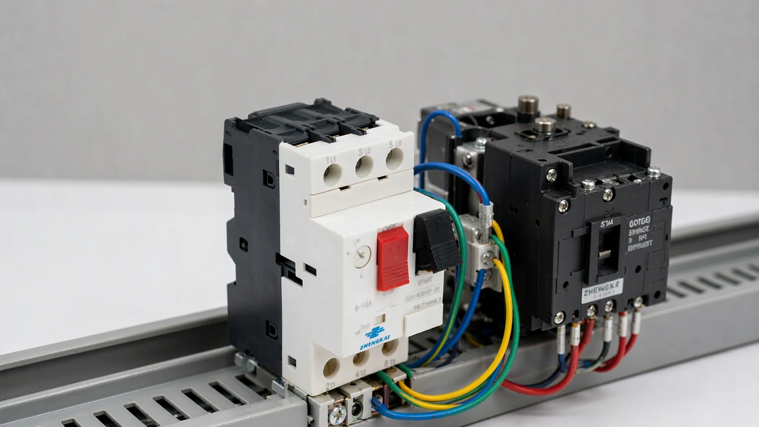
The chart works in three steps.
One direction of lookup is covered here: motor → current → model. If you already have a model in hand and want to know which motors it protects, use the reverse lookup in our MPCB rating and selection chart, which lists every GV2-M model with its setting range.
Typical values for standard 4-pole, 50 Hz three-phase cage induction motors in the IEC power series (IEC 60072-1). The overload setting equals the motor’s full load current; see the next section for when to adjust it.
| Motor power | FLA at 400 V (A) | FLA at 415 V (A) | Overload setting (A) | Recommended MPCB | Setting range (A) |
|---|---|---|---|---|---|
| 0.37 kW / 0.5 hp | 1.1 | 1.1 | 1.1 | GV2M06C | 1.0–1.6 |
| 0.55 kW / 0.75 hp | 1.4 | 1.3 | 1.4 | GV2M06C | 1.0–1.6 |
| 0.75 kW / 1 hp | 1.9 | 1.8 | 1.9 | GV2M07C | 1.6–2.5 |
| 1.1 kW / 1.5 hp | 2.6 | 2.5 | 2.6 | GV2M08C | 2.5–4.0 |
| 1.5 kW / 2 hp | 3.5 | 3.4 | 3.5 | GV2M08C | 2.5–4.0 |
| 2.2 kW / 3 hp | 5.0 | 4.8 | 5.0 | GV2M10C | 4.0–6.3 |
| 3 kW / 4 hp | 6.6 | 6.4 | 6.6 | GV2M14C | 6.0–10.0 |
| 4 kW / 5.5 hp | 8.5 | 8.2 | 8.5 | GV2M14C | 6.0–10.0 |
| 5.5 kW / 7.5 hp | 11.5 | 11.1 | 11.5 | GV2M18C | 9.0–14.0 |
| 7.5 kW / 10 hp | 14.5 | 14.0 | 14.5 | GV2M20C | 13.0–18.0 |
| 11 kW / 15 hp | 22 | 21.2 | 22 | GV2M22C | 20.0–25.0 |
| 15 kW / 20 hp | 29 | 28 | 29 | GV2M32C | 24.0–32.0 |
| 18.5 kW / 25 hp | 35 | 33.7 | — | Please contact us for a suitable MPCB selection | — |
| 22 kW / 30 hp | 41 | 39.5 | 41 | GV3-M | 40–63 |
| 30 kW / 40 hp | 55 | 53 | 55 | GV3-M | 40–63 |
| 37 kW / 50 hp | 66 | 63.6 | — | Outside GV2-M / GV3-M range | — |
| 45 kW / 60 hp | 80 | 77.1 | — | Outside GV2-M / GV3-M range | — |
| 55 kW / 75 hp | 98 | 94.5 | — | Outside GV2-M / GV3-M range | — |
| 75 kW / 100 hp | 135 | 130.1 | — | Outside GV2-M / GV3-M range | — |
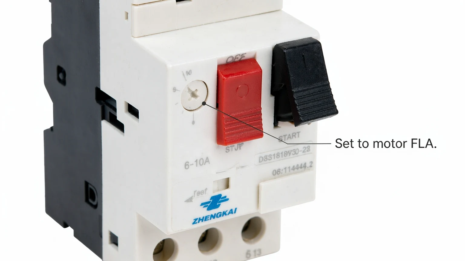
An MPCB does two jobs in one frame: a magnetic trip for short circuits, which is fixed and not adjustable, and a thermal trip for overload, which is the dial you set. The dial is the only part of the protection you configure, and it is the part that keeps the winding from cooking.
Set it to the motor’s full load current. That is the whole rule, and the table above already gives you the number in the Overload setting column.
The setting is not a margin you add on top of the rated current. Winding insulation is rated for a defined temperature rise at rated current; a dial set 20% above FLA lets the motor sit 20% over current indefinitely, and the first sign of trouble is usually the smell of burnt varnish rather than a trip. If a motor trips in normal service with the dial set correctly, measure the actual running current with a clamp meter before touching the setting — the usual causes are a supply voltage at the bottom of tolerance, a mechanical overload on the driven equipment, or a motor that was already the wrong size for the duty.
Two adjustments are legitimate and both are small:
Three worked examples, all taken from the chart above:
| Motor | FLA at 400 V | Dial setting | Model | Range |
|---|---|---|---|---|
| 2.2 kW / 3 hp | 5.0 A | 5.0 A | GV2M10C | 4.0–6.3 A |
| 7.5 kW / 10 hp | 14.5 A | 14.5 A | GV2M20C | 13.0–18.0 A |
| 15 kW / 20 hp | 29 A | 29 A | GV2M32C | 24.0–32.0 A |
If you are choosing between an MPCB and a separate thermal overload relay for the same job, the comparison is set out in MPCB vs thermal overload relay. For the wider family of devices that protect a motor — relays, MPCBs and winding sensors — see motor overload protection devices.
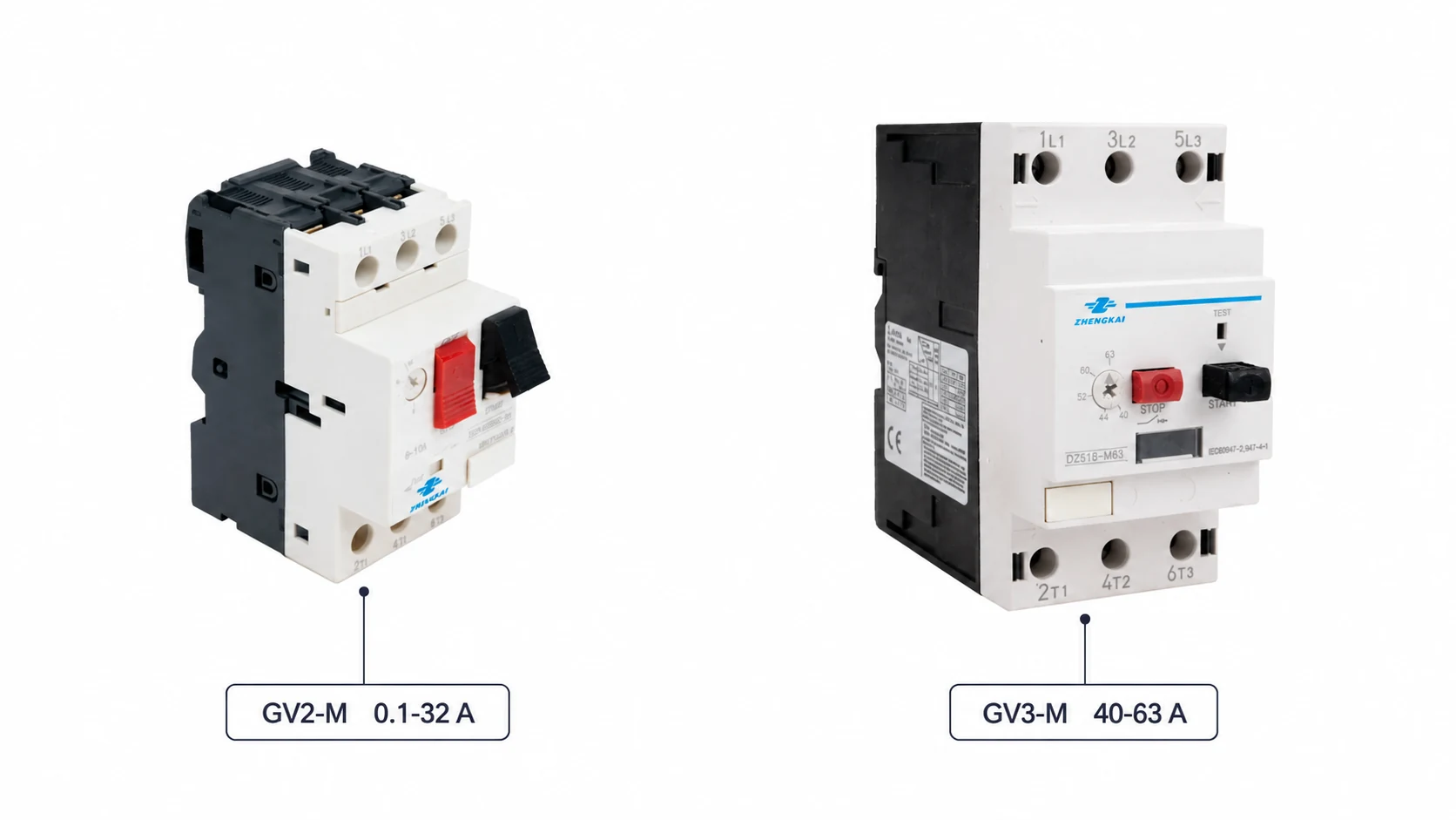
Our motor protection circuit breakers run in two series:
Three rows in the chart deserve a straight explanation rather than a forced fit.
A standard 18.5 kW, 400 V motor draws about 35 A. GV2-M stops at 32 A and GV3-M starts at 40 A, so 35 A falls between the two families and neither one covers it as a single unit. Rather than list a model that would not hold the setting, the chart says contact us. If you are working on an 18.5 kW drive, tell us the nameplate current and the starting method and we will come back with the arrangement that fits, including combinations outside the two series above. The same applies if your project uses 36 A or 38 A frames we have not listed.
41 A is inside GV3-M’s 40–63 A span, so the model protects the motor — but the dial sits near the bottom of its travel. Check that the motor’s measured running current is comfortably above 40 A before committing; if a specific motor idles lower than the published figure, the next size down may be the better fit.
From 37 kW upwards the current exceeds the 63 A top of GV3-M. We have left those rows in the table because the current figures are useful reference values when you are sketching out a panel, but they need a different class of protection. We do not list a model we cannot supply.
The complete range, with settings and order codes, is on the MPCB product range page. If you already know which model you want and need the motors it covers, start from the MPCB rating and selection chart instead.
The same data — full load current at 400 V and 415 V, the overload setting and the model — is available as a single-page PDF for the panel shop or the site folder.
Download the 3-phase motor full load current chart (PDF, 1 page)
Need a model that is not in the table, or a current value for a voltage we have not covered? Send us the motor nameplate and the duty and we will confirm a selection. Contact us — most selection questions are answered within one working day.
3 hp is 2.2 kW. At 400 V a standard motor draws about 5 A, so GV2M10C with its 4.0–6.3 A range covers it. Set the dial to 5 A. At 415 V the current is 4.8 A and the same model still applies.
In practice yes. Full load amps (FLA), full load current (FLC) and rated current all refer to the current the motor draws at its rated output on the nameplate. Some catalogues use Ie, the rated operational current, for the same figure. The one place to be careful is a protector’s own current rating — that describes the device, not the motor.
Only in the small, deliberate way described above — 1.05 × FLA for a hot location or a long start. Setting it higher to stop nuisance tripping does not solve the underlying problem; it removes the protection and leaves the winding to fail later. Measure the running current first.
Usually not. For the same power a 415 V motor draws about 3.5% less current than a 400 V one, so a model chosen from the 400 V column covers both. Choose the model on the 400 V current and set the dial to the 415 V value.
Take the higher row. Protection is sized from current, and the nearest catalogue power rating is a marketing figure, not an electrical one. If the difference matters for your application, measure the actual running current and select from that.
More on how the device is chosen in context: how to select an MPCB for a 3-phase motor, and MPCB vs MCB vs MCCB for where the motor protection breaker sits among the other breakers in a panel.
The current values in the chart are typical figures for standard motors, cross-checked against three published motor data sources: a UK distributor’s full load current table at 400 V, an Indian reference table at 415 V with stated power factor and efficiency, and a major manufacturer’s published coordination table for standard AC-3 motor currents. Above 18.5 kW the first and third of these agree row for row, which is the main reason for the confidence in this range. The 415 V column was derived from the 400 V figures by voltage ratio and matches the independent 415 V table.
One row needed a judgement. For 7.5 kW the three sources give 14.0 A, 14.5 A and 15.5 A. The difference is not an error — it is the assumed efficiency class. The chart uses 14.5 A, which corresponds to the IE3 motors that dominate current IEC-market supply. If you are replacing an older, lower-efficiency motor, its nameplate current may sit nearer the 15.5 A end, and the next model up in the same range will usually be the safer choice.
Two further caveats. The 0.55 kW row is a calculated value: the published tables do not carry that rating, so it was derived from power, voltage, power factor and efficiency, and it matches the setting range a major manufacturer assigns to that motor size. And a motor’s starting current is five to eight times its full load current regardless of what this table says — the table sizes the overload protection, not the contactor or the short-circuit trip.
Finally, the rule that overrides everything above: your motor’s nameplate is the authority. This chart is for pre-selection and for checking a selection someone else has made.